
|
|
Post Reply 
|
| Author | |
pangster 
Advanced Newbie 
Joined: 07-June-2010 Status: Offline Points: 37 |
 Post Options Post Options
") Thanks(0) Thanks(0)
 Quote Reply Quote Reply
 Topic: HOW TO: BMW Z3/E36 Custom EL dials Topic: HOW TO: BMW Z3/E36 Custom EL dialsPosted: 12-June-2010 at 14:13 |
|
TOOLS/EQUIPMENT NEEDED:
* Sharp knife and cutting board * TomTom/Sat nav sucker (makes removing the gauge binnacle a doddle) * Soldering iron (with fine nib) and solder * Dremel / drill or cutting tool i.e stanley knife etc * Belt hole punch * UHT spray glue or thin double sided tape or similar * Small screwdriver * Torx screwdriver (or whatever screws hold your gauge cluster in usually a T20 or a T25, but some have phillips!) * Precision Torx screwdrivers (T10, T8 and T6 are useful) * Table cloth/soft cloth * Crimper and crimps/scotch locks or t-tap connectors * Insulating tape * Ruler/measuring tape * Clear plastic and CD pen or tracing paper and pencil * Fork * Cable ties (optional) * Thin nose pliers * 9v square 2 pin battery (for testing purposes) * 5"x6" EL panels (x2) and 12v transformer * Dials of your choice (I used Lockwood, you could use any dials including stock) * Y lead to run 2 EL panels from 1 invertor * Dial paint or pen (optional) STEP 1: Removing the gauge cluster from your car: This guide assumes you know how to remove your dials from your car - there's plenty of guides on this on the net so I didn't see the point into going into this step in any detail, but I've given a brief description below. In essence you take your T20/T25 screwdriver (there seems to be a variance in screws used across the models!) and unscrew the 2 screws holding your clocks in place (highlighted in green on the below photo):  N.B. If you have a compact or Z3 this can be achieved with a careful bit of maneuvering without removing the steering wheel! - Once both screws have been removed, draw the dash forward (you might find your sat nav sucker comes in useful here!). Once the dash has been drawn forward - have a look round the back and you will see 3 multi plugs (white, blue and black). These all have lock levers which hold them in place and can be simply unlocked by pressing gently down on the retainer tab with your small screwdriver and the sliding the lever upwards. STEP 2: Separating the gauge cluster: You should now have the gauge cluster removed from the car. Spread your cloth out on your work surface and place the cluster face down (clear plastic on the cloth). The reason you're using the cloth is to make sure you don't scratch the face! There are 5 torx screws that hold the back of the cluster onto the clear window and black plastic section. Unfortunately the picture I took at the time came out a little blurry!! - so I've tried to show the locations in red on this picture below:  Take your T10 screwdriver and remove all 5 screws (the 2 in the corners and the 3 in the centre). You should now be able to separate the blue back cover from the rest of the cluster. There are now 3 thumb screws which clamps the black plastic surround to the dials (these are shown below in red):  Turn these through 180 degrees (I found using thin nose pliers helped enormously here!) and the front part (clear plastic screen and black plastic surround) will come away from the dials. You should now have something that looks similar to this:  STEP 3: Removing dials and needles: This step could vary depending on the dials you're fitting. In my case I decided to remove the stock dial face. To do this, you first need to remove the needles. BEFORE removing the needles it is strongly advisable to make a note of their exact position. To do this you need to remove the stop pegs for the speedo and rev counter (your think nose pliers will come in handy here). You'll notice that both needles drop down slightly - it is this starting position you want to take note of! I simply measured from the tip of the needles to static parts of the cluster (i.e. screws etc). Once you're happy you've noted all of the needles current positions you can go ahead and remove them. I took my fork and using the middle 2 prongs, slid it gently under the base of the needle (ensuring I was applying the same pressure across it's base) and then gently prise the needles up. It's important you don't force them as this could bend/damage them. There will be a slight resistance but you should be fine as long as you apply pressure evenly. Once all the needles are removed you can then remove the gauge face (this is just stuck down onto the clear plastic backing with a little adhesive and should just lift straight off). STEP 4: Preparing your new dials (EL template): I guess this is when the arty/craft part of the project begins! My Lockwood dials came in 2 separate halves which made this slightly easier as I was working with 2 x EL panels (1 for each side). Take your new dial and offer it up to your EL panel: 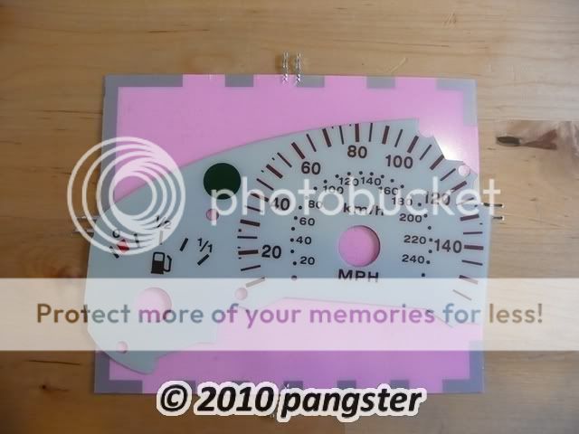 You need to decide the best position for this. Bear in mind that when you're cutting round the EL panel you need to leave yourself a pair of connectors to connect to!! i.e. do not place the gauge in the middle of the panel and cut round it! NB where you also see the silver strips on the edge of the panel, these are non light emitting so also bear this in mind! I position min at approximately 45 degrees on the panel which meant that I had 2 connectors coming out from the top (round about th 100 mph mark) as can be seen here:   You'll also note from the above that I have a silver strip in the bottom left hand corner (this is fine as well as there is nothing that needs to be illuminated here). STEP 5: Finishing off your EL dials: You now have a rough template for your EL backing for your dials. You now need to ensure that all of the holes and windows required to let light pass through from the back or to allow the needles to be fitted are cut out. To achieve this I placed the dial face on my EL template and took my belt hole punch (selected the appropriate size hole and punched the EL template). For the larger holes for the needles - I placed the dial face and EL template on my cutting mat and cut slowly with a very sharp craft knife - your EL template backing should now look something like this:  You still need to cut out the windows for your indicator and for the fuel tank/temp (depending on which side you're doing) - I found the best way for this was to place the dial under a clear piece of plastic and trace round these areas (tracing paper would work equally as well):  I then transferred these onto the EL backing template and cut them out (TIP: you can use the bigger hole for the needle (speedo or rev counter) as a circle template for your indicator to ensure you get a perfectly smooth and round circle (they're the same size) - you should now be left with this:  It might be a good idea at this stage to check how they'll actually look (to make sure you're happy with them and make any final tweaks) - to do this just hook up your 9v battery to the transformer and connect to the EL backing terminals:  Once you're happy with the results, you now take your glue or double sided tape (I used UHT mounting spray glue) and glue the dial face to the back EL panel (apply some pressure to ensure you get the dial and panel as flat as possible. Now repeat the above steps for the other side! STEP 6: Soldering the leads/tails to your EL dial terminals: You now need to solder the leads that run from your EL dials to your harness/12v transformer. Take your soldering iron and solder, tin the wires for the tails and then solder onto your terminals on the EL panels:    STEP 7: Installing EL dials onto cluster: Offer your new EL dials up to your clear plastic panel/backing - make sure you're happy with the fit/position and plan how you're going to run the wires from the EL terminals. Apply a little adhesive to the back of the EL panel and position on the clear plastic panel. Install your needles (making sure you position them based on the notes/measurements you took earlier):   Now you need to take the clear plastic window/black surround and re-attach it to your cluster - this is the same as detailed in the removal step before where you offer both parts up and the twist the 3 thumb screws through 180 degrees:  Flip the cluster over onto it's face and again place down on the towel/cloth to ensure you don't scratch the clear plastic. You should now see your 2 leads running from your EL panels. You need to decide the best way to route these. In my case I had one coming out the top and one coming out of the bottom (highlighted in yellow below):  Based on where your terminals are and how you intend running your leads will decide where you need to modify the rear blue plastic cover. I took my Dremel and made a small incision in the top for my first lead and then made a slight groove in the bottom for my second lead (shown in yellow below):  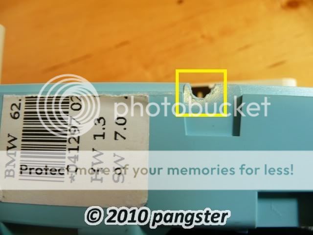 You now need to feed your wires through the cuts/grooves you've made and then screw the unit back together again (5 x torx screws):   And then take both leads and connect to your Y lead which will allow you to run both panels from 1 x 12v transformer:  STEP 8: Installing EL dials/cluster into your car: You only have 2 wires you need to fit in order to install your dials. You need a ground and a switched live. I decided given the location of the cluster that the best source for both of these would be from the stereo harness. The reason for this is that it gives you a few choices as to where you want to tap in for the switched live. I was lucky enough to have an Alpine stereo fitted which came with a spare switched live lead (so I justed needed a bullet connector) but I also contemplated tapping into the illumination wire instead so that it came on with the headlights and could be adjusted. I chose the spare switched live because I'm lazy! LOL! If you want to use your stereo harness then the first step is to remove your stereo and then feed the wires through from the cluster to the opening for your stereo:   You can see from the last photo above that I had already tapped in to the ground with a scotch lock. In hindsight I would have used t-tap connectors to do this but had none to hand!! I then identified which switched live source I was going to use (as mentioned before my headunit came with a spare one): 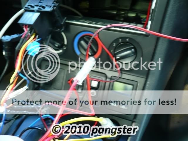 Which meant all I needed to do was add a bullet connector to the live from the 12v transformer and connect it and that completed the wiring:  You now need to feed all the wires back behind the dash. I used cable ties at this point to tidy it up a bit. Refit your stereo. Now plug the 3 multi plug connectors back into your gauge cluster (black, blue and white) and make sure they're secure. It might be a good idea at this point to check to make sure everything is working. Once you're happy that everything is fine - go ahead and refit the gauge cluster back into the dash with the 2 screws removed before. STEP 9: The end result: You should have something that looks like this:   
|
|

1998 BMW Z3 2.8 Roadster 1998 BMW 316i Compact (E36) |
|
 |
|
| Sponsored Links | |
|
|
|
sailorbaz
Really Senior Member II 
(Former) Scottish Region Wean Joined: 02-August-2003 Location: Northern Ireland Status: Offline Points: 961 |
Post Options
Thanks(0)
Quote Reply
Posted: 13-June-2010 at 14:02 |
|
Excellent write up mate, top work.

|
|
|
|
|
pangster
Advanced Newbie
Joined: 07-June-2010 Status: Offline Points: 37 |
Post Options
Thanks(0)
Quote Reply
Posted: 13-June-2010 at 14:37 |
cheers!! - hopefully others will find it useful as the stock lighting is pretty poor!! |
|
|
1998 BMW Z3 2.8 Roadster 1998 BMW 316i Compact (E36) |
|
|
|
|
pangster
Advanced Newbie
Joined: 07-June-2010 Status: Offline Points: 37 |
Post Options
Thanks(0)
Quote Reply
Posted: 17-June-2010 at 22:49 |
|
Thought I'd post a comparison shot of old stock dials v new custom EL dials:

|
|
|
1998 BMW Z3 2.8 Roadster 1998 BMW 316i Compact (E36) |
|
|
|
|
Post Reply
|
|

|
| Forum Jump | Forum Permissions You cannot post new topics in this forum You cannot reply to topics in this forum You cannot delete your posts in this forum You cannot edit your posts in this forum You cannot create polls in this forum You cannot vote in polls in this forum |


 HOW TO: BMW Z3/E36 Custom EL dials
 Topic Options
 sailorbaz wrote: